Inconsistent line width in ThicknessSpace.Pixels

Avatar
  • updated
  • Under Review

Hey,

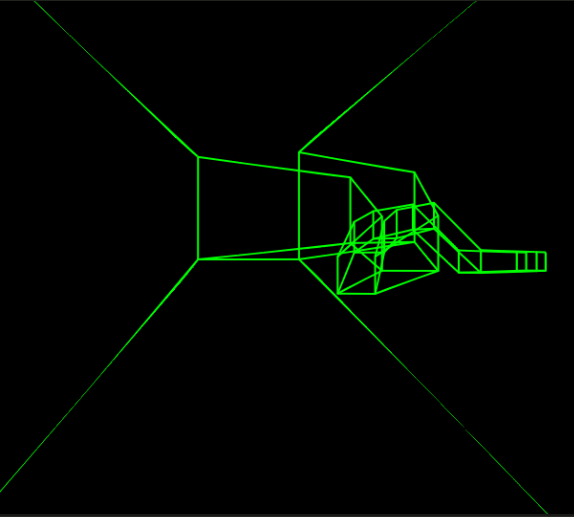
I want to use PolyLine and Line to draw a virtual tunnel that I want to fly through. To make the lines have an equal thickness no matter how far away from the camera they are I am using the ThicknessSpace.Pixels (as said in the documentation) but unfortunately they are not of equal thickness as you can see in the picture. I draw all lines in Immediate-Drawing Mode to the Main Cam via OnPostRender. 

Image 190

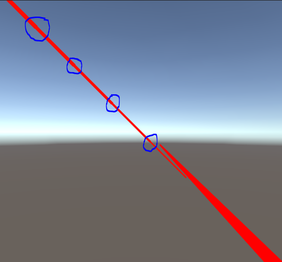
I also tried to reconstruct this in a completely new, empty project with VR disabled, however, the problem keeps occurring but in a different style (see figure below). Both lines use pixel space, the lower right is a polyline, the upper left is a normal line, both coming from behind the camera and going in z-direction and get smaller the further away from the camera. The upper left even has this cascading thickness effect I have encircled. 

Image 191

Would be great if line thickness would be truly independent from camera distance! :)

Thanks in advance for your reply!

Reporting a bug? please specify Unity version:
2019.4.11f1
Reporting a bug? please specify Shapes version:
2.3.2
Reporting a bug? please specify Render Pipeline:
Avatar
Freya Holmér creator
  • Under Review

this only happens when one of the endpoints are off-screen correct?

Avatar
timbrando

Yeah, when one point is out of the camera frustum, I would say. 

Avatar
Freya Holmér creator

so, this is a pretty hard problem in general

In case you're curious about details - everything in Shapes is in world space, and for pixel lines, I have to answer the question "how wide should this be in meters, in order for it to be x pixels wide?". If the endpoint is visible on screen, this is a relatively easy question to answer. if it's off-screen on the other hand, it's way more complicated.

It's not impossible, I will look into this at some point! a "workaround" for now is to use meter-based thickness if it works in your project

Avatar
timbrando

Hi,

thanks for the reply! I think I understand what you mean. Would be great if we could modify screen pixels directly in Unity. This would make the whole drawing of primitives a lot easier probably.

But since our current graphics library is based on OpenGL where you can draw lines with constant pixel width it would be great if this is an option for Unity/Shapes, too.

Currently we are trying to use it in combination with the HoloLens 2 where the result with pixel space looks quite okay, I think. In the peripheral field of view human's perception isn't that good anyway...

Nonetheless, I hope that you stay with it and can fix this issue sooner or later but in my opinion this is not suuuper urgent.

Regards

Avatar
JohannesMP

Apologies for the bump. I originally posted a reply here, but after thinking about it I think the issue I am seeing seems to be different enough that I deleted my original reply and made a separate topic for it: https://shapes.userecho.com/en/communities/1/topics/207-

Avatar
JohannesMP

I spent a bit of time poking at this in Shapes 3.0.0 with a test case: a 1 unit long Volumetric line segment with a thickness of 50 pixels, oscillating forward and back by +/- 0.5 units in its object's local space to make visualizing line thickness variations easier. I overlay two spheres, also in pixel space, on the start and end points respectively to compare thickness against. You can specify how many line segments are displayed between the oscillating start and end points. 

My assumption was that while there might be slight variations between the geometry of a sphere and end caps of line segments, by and large they should appear to have approximately the same radius on the screen, and that inconsistencies with the line segment mismatching should only occur when one point of the line segment passes behind the camera.

However that does not seem to be the case, and there can be extreme variations between the sphere and the end cap sizes even when no part of the line segments are behind the camera's viewing plane:

In this case for example the vertical position of the line segment's end point in view space appears to drastically change its perceived thickness the further it is from the middle, with an apparent bias to being larger at the top and smaller at the bottom that is amplified the closer you are to the points. Any idea what might be causing this?

Here is some additional footage of me just messing around with it. Much of the behavior is expected (line thickness varying as one end point passes behind the camera): 

Source code here:

using UnityEngine;
using Shapes;

[ExecuteAlways]
public class ViewplaneLineIntersection : ImmediateModeShapeDrawer
{
    private const float THICKNESS = 50;

    [Min(1)] public int segments = 1;

    // Update Logic
    private float _time;
    private Vector3 _posStart;
    private Vector3 _posEnd;
    private void Update()
    {
        float offset = Mathf.Sin(_time);
        _posStart = new Vector3(0, 0, 1 + offset);
        _posEnd = new Vector3(0, 0,  -1 + offset);
        if (!Application.isPlaying) return;
        // Ensure we behave nicely when pausing and unpausing
        _time += Mathf.Min(Time.unscaledDeltaTime, 1/60f);
    }
    
    // Draw Logic
    public override void DrawShapes(Camera cam)
    {
        using (Draw.Command(cam))
        {
            Draw.ResetAllDrawStates();
            Draw.Matrix = transform.localToWorldMatrix;
            Draw.BlendMode = ShapesBlendMode.Transparent;
            Draw.LineGeometry = LineGeometry.Volumetric3D;
            Draw.LineThicknessSpace = ThicknessSpace.Pixels;
            Draw.LineThickness = THICKNESS;

            // Draw Line Segments
            for (int i = 0; i < segments; ++i)
            {
                float startParam01 = i / (float) (segments);
                float endParam01 = (i + 1) / (float) (segments);
                Vector3 curPosStart = Vector3.Lerp(_posStart, _posEnd, startParam01);
                Vector3 curPosEnd = Vector3.Lerp(_posStart, _posEnd, endParam01);
                Color curColor = FixGammaColor(Color.HSVToRGB(startParam01, 0.95f, 0.75f));
                Draw.Line(curPosStart, curPosEnd, curColor, curColor);
            }

            // Draw Debug end spheres
            Draw.BlendMode = ShapesBlendMode.Screen;
            Draw.SphereRadiusSpace = ThicknessSpace.Pixels;
            Draw.SphereRadius = THICKNESS / 2;
            var color = Color.white;
            color.a = 0.1f;
            Draw.Sphere(_posStart, color);
            Draw.Sphere(_posEnd, color);
        }
    }

   private static Color FixGammaColor(Color color) 
        => QualitySettings.activeColorSpace == ColorSpace.Linear ? color.linear : color;
}
Avatar
Freya Holmér creator

the issue above was fixed in 3.1.0, OP's issue is still present! looking into it now

Avatar
JohannesMP

Looking at OP's issue, it seems that the only time screenspace line thickness is incorrect is when the line between any two consecutive points passes through the camera view plane. In other words, if one point is in front, and the other is behind the camera.

I was curious if when this happens we manually inject a vertex right on the view plane, so I wrote a helper function that modifies a given PolylinePath so that for any two points where one is in front and one is behind the camera it inserts a point between them that is right on the view plane:

// Overload without LocalToWorld Matrix
private static void PolylineScreenThicknessFix(PolylinePath path, Camera cam) =>
PolylineScreenThicknessFix(path, cam, Matrix4x4.identity);

private static List<PolylinePoint> _pointScratch = new List<PolylinePoint>();
private static void PolylineScreenThicknessFix(
PolylinePath path, Camera cam, Matrix4x4 localToWorld)
{
if (cam == null || path.Count < 2) return;

Matrix4x4 localToCamNearPlane = Matrix4x4.Translate(new Vector3(0, 0, -cam.nearClipPlane)) *
cam.transform.worldToLocalMatrix * localToWorld;

PolylinePoint prev = path[0];
float prevDist = localToCamNearPlane.MultiplyPoint3x4(prev.point).z;
_pointScratch.Clear();
_pointScratch.Add(prev);
for (int pathIndex = 1; pathIndex < path.Count; ++pathIndex)
{
PolylinePoint cur = path[pathIndex];

float curDist = localToCamNearPlane.MultiplyPoint3x4(cur.point).z;
if (prevDist > 0 != curDist > 0)
{
float midParam = Mathf.InverseLerp(prevDist, curDist, 0);
Vector3 midPoint = Vector3.LerpUnclamped(prev.point, cur.point, midParam);
float midThickness = Mathf.LerpUnclamped(prev.thickness, cur.thickness, midParam);
Color midColor = Color.LerpUnclamped(prev.color, cur.color, midParam);
_pointScratch.Add(new PolylinePoint(midPoint, midColor, midThickness));
}
_pointScratch.Add(cur);

prev = cur;
prevDist = curDist;
}

if (_pointScratch.Count == path.Count) return;

path.ClearAllPoints();
path.AddPoints(_pointScratch);
}

I tested this out in a scene with two PolylinePaths of two points each -The green/yellow line is the default behavior, and the blue/cyan one inserts a point on the view plane (which for debugging I'm coloring red so it's easy to see)

The full testing code used in this example can be found here: https://gist.github.com/JohannesMP/b1f96770b55b1f9668e87ab536aae525 (has been slightly modified since the screen capture above to color the line behind the camera black so you can more clearly see the division point)

Of course rebuilding the PolylinePath like this is not the most performant, but as a proof of concept it seems to achieve the desired result - the thickness of the blue line appears to remain consistent regardless of if it might cross through the camera plane or not.

Maybe something more efficient could be implemented natively in Shapes?